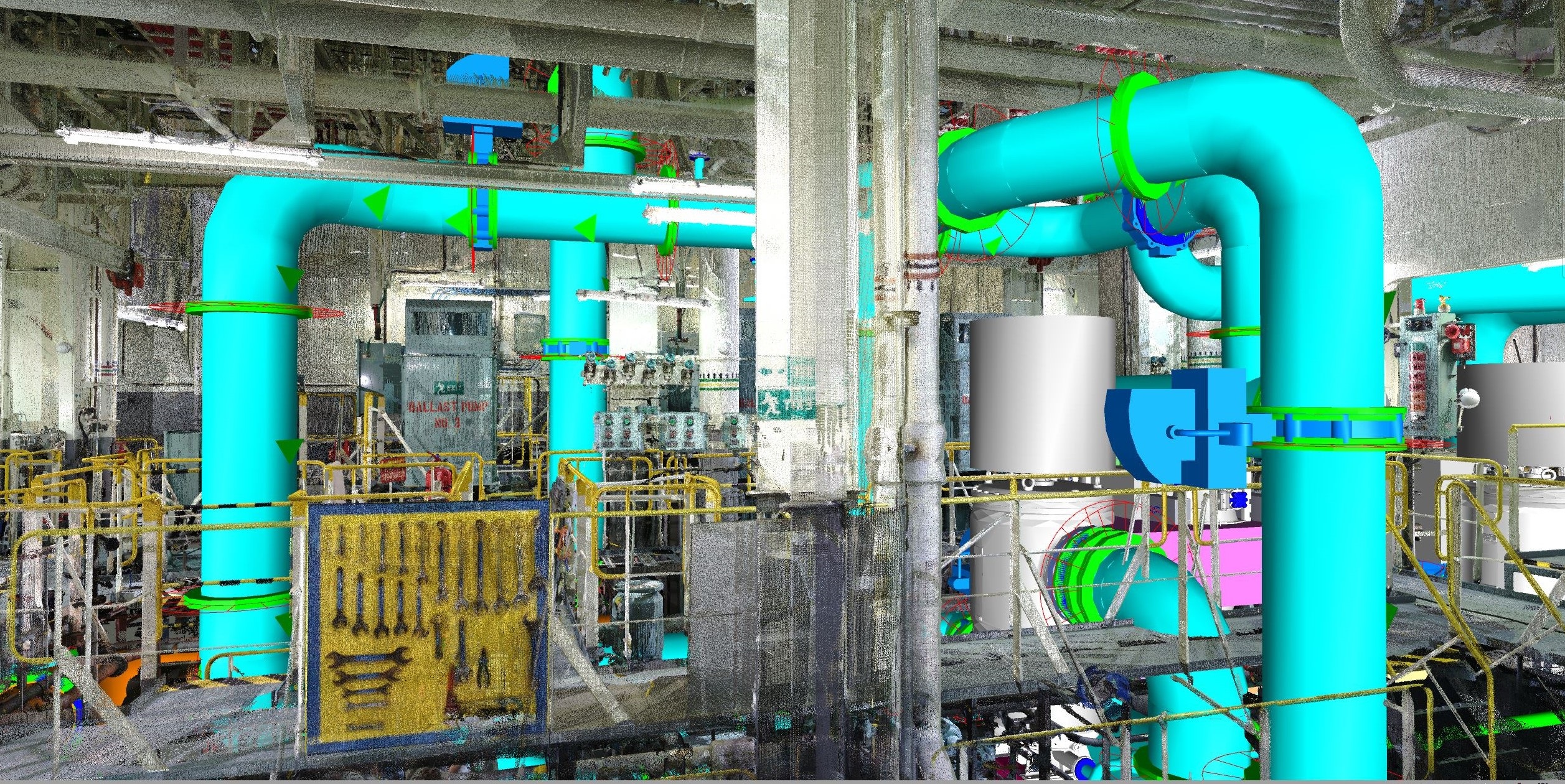
Reverse engineering is a process that involves measuring a physical object and reconstructing it as a 3D model to recover the design intent — a perfect reconstruction of the original design — in terms of simple analytical surfaces (planes, cylinders, etc.) and freeform surfaces (NURBS) in order to produce a new reference CAD model.
The reasons for reverse engineering are multiple: to replace damaged components (for which CAD models are nonexistent), to update obsolete parts, to fit new parts into a current assembly or environment, to generate new manufacturing plans, or simply to analyze competitors’ product features. 3D scanners are generally the preferred technology for extracting dimensional information and representing it as a point cloud or an automatic and instant mesh.
How we approach reverse engineering at Panoptic
Our workflow takes 3D scan data — whether a point cloud or a mesh — and converts it into a fully parametric CAD model in SOLIDWORKS or Autodesk Inventor. The difference matters: a raw scan mesh is a static snapshot you cannot edit, while a parametric model is a working engineering document. Dimensions can be changed, features can be modified, and the file can be used directly for manufacturing, redesign or further development.
Depending on the project, we deliver:
– Parametric 3D CAD models reconstructed from scan data
– 2D technical drawings prepared to industry standards
– Geometry verification reports comparing the CAD model against the original scan
– Recommendations for design improvements or manufacturing optimization
Typical use cases we have supported include legacy spare parts where original drawings no longer exist, documentation of existing machinery before retrofit or modification, and adaptation of components from one system for compatibility with another.
Have a part that needs to be scanned and modeled? Send us the details and we will scope the project for you.


 info@panoptic.ba
 +387 61 411 501


